top of page
1. Frame Depth
The most important factor in determining the frame depth is the frame channel. The second element is the selection of the barrier width , this selection depends on the level you want the Uf values of the frame to be, this selection should be determined in your regional and market research, the third element is the corner wedge gap is also an important measurement, this gap determines what kind of accessory the frame can be combined with, in the door-window section, which is our subject, corner joints are provided with 45 degree joints, these joints can also be made as 90 degree vertical joints in different joinery types.
1-Aluminum channel
It is an accessory channel designed for aluminum profiles, it has different dimensions and accessory manufacturers for aluminum doors and windows produce their systems by taking these dimensions into account, I will give detailed information about the subject in the accessory selection section.
Components
2-PVC channel
It is an accessory channel designed for PVC profile systems. It has different dimensions and PVC group accessory manufacturers produce their systems by taking these dimensions into account. This accessory group has been integrated into the aluminum system due to various market demands. Therefore, I will give more detailed information about the two accessory groups in the accessory selection section.


Polyamide barriers are available in different sizes from 10mm to 55mm, with many options in different forms such as flat, curved, with seal slots and with tabs.

A
B
C
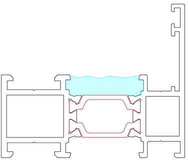
The most important factor affecting the frame design is the middle insulation gasket. The location of this gasket and the way it is attached to the frame are effective in the selection of the barrier. As seen in the figure on the side, 3 types of barriers are used in barriers of the same width.
A: Under the middle insulation gasket, a hump barrier was used and the necessary slot for the gasket to pass through was provided by making a nail in the aluminum profile.
B : A single-claw humpback barrier was used, one of the slots required for the seal to pass was provided by the tab on the barrier, and the other tab was provided by making a tab on the aluminum profile in accordance with the barrier tab.
C: A channeled barrier was used under the middle insulation gasket, the gasket was inserted into this barrier, and no additional tab was made on the aluminum.
As can be seen, there can be more than one alternative, these types of barrier options make your system distinctive from other companies, system companies can get profile registration from patent institutions when the design of their systems is completed, in this frame, in order for our own profile not to be rejected in a profile registration, these more than one distinctive features must be present.

Case channel size
Internal profile
External profile
-
Once the necessary research is done and the frame channel size is determined, we can start our design from this point.
-
If we have determined the middle seal insertion slot and it will create an aluminum tab detail as in the figure, we can make a tab with a depth of not less than 1.5 mm, through which the seal can pass but which will not come out very easily.
-
One of the most important points is the location of the barrier slot; in order for the discs of the barrier tightening machine to fit and tighten well, the distance from the edge where the disc will approach to the tip of the tightening tab must be at least 3mm.
-
By doing the above three items and placing them in the drawings, the gap inside the profile will be removed, of course it is necessary to put the profile wall thicknesses here as well.
-
After determining the barrier width we will use, we need to determine the barrier tightening distance within the outer profile and the distance to the outer part of the frame profile after making the tab detail for the middle seal slot.
-
The final dimension of the outer frame profile is determined by its relationship with the sash profile.

-
Detail A is a 3-seal system and there is an insulation gasket outside the frame. This gasket will take up some space due to its thickness and pressing distance. This system is the most common system in Turkiye, and the reason for this is that it is thought to provide more water insulation. I will come back to this topic and give more detailed information.
A

B
-
Detail B is a 2-seal system and there is no insulation gasket outside the case. There is a 1mm distance between the wing and the frame. Therefore, it allows the frame width to be reduced by 1.5-2mm. I will give more information about the advantages of the 2-seal system in the following sections.
Placing the barrier housing in its exact place

-
Technoform standard barrier slot dimensions.

-
The situation where the barrier tabs are up


-
The barrier location is determined by the design of the middle seal and the water discharge line in fixed cases. If the barrier slots are positioned below the water discharge area, water will accumulate in this slot under the fixed glass and if we take the aluminum tabs with a milling cutter and open a discharge area, the barrier line will not be able to drain some of the accumulated water because it is below the water discharge area line.
Water accumulated in the seal housing
Water drainage area
-
Barrier tabs positioned below the water discharge area
-
Even if the aluminum wick tab is milled to the end for water drainage, it will not be able to drain the water on its own since the barrier line remains below the water drainage area. In this frame, if a test is to be performed, even if you get the desired water performance, the water seen in these areas during controlled disassembly will be classified as one value below the value you have obtained. Apart from this, the most important point is that the water accumulated here will go down to the profile from the capillary points and will damage the insulation over time.

-
Remaining water after discharge
-
Although the barrier tabs are above the water discharge area, there may not be enough distance for the seal tabs to pass easily into place, so when determining the location of the barrier slot, it is necessary to look at the design of the middle seal. At least after leaving a place for the fit and a space for the seal tab to flex and pass, the seal design can be looked at later. I will explain this point in more detail regarding the seal design.
In case of corner wedge gap in profiles being combined with corner press, "A" height measurement is important to use the same wedge size, this "B1" and "B2" dimensions may be different, this can be done only by changing the cutting size of the wedge.
Corner wedges can be designed to be suitable for both press and pin connection systems. In this way, two types of corner joining operations can be performed with a single wedge. In this case, the width of the "B2" dimension can be adjusted to make a connection with a 5mm pin.
In compression connection, since it is possible to find a connection accessory only according to the "B1" space, compression accessory can be considered for the "B1" space and pin connection for the "B2" space.
Corner wedge for press
Corner wedge for press + pin connection

Frame Channel size
Siegenia
case channel dimensions
Roto-Frank
frame channel dimensions
The dimensions of the frame channel are determined by the accessory brand you will choose, if we talk specifically about Euro standard channel dimensions, they may differ from each other with very small nuances in different brands, but these differences can remain within the assembly tolerances, in summary, the standard channels of accessory manufacturers in the Euro zone are the same with each other except for small nuances.
There are different common standard channel sizes, you can choose to access this accessory according to the easy availability criterion or your marketing and sales goals, you should definitely have your concept designs approved by one or more accessory suppliers, it may not be desired to work with a single accessory brand in the joinery produced according to the design you will make due to different reasons, for this reason, the accessory channel size in the design made should be compatible with the channel structures of different brands, this profile will provide great flexibility for the system house.
The frame channel is also used as the slot where the glazing bead enters, therefore small angles are given in the profile to allow the bead to enter more easily. These angles should never change the channel size and form.

As can be seen, an accessory brand with the widest dealer network in Turkiye has at least three types of channels for aluminum. Although it can produce according to these channels, there is no stock in dealers or distributors for each channel size. This is why the stock cost for hundreds of different mechanism sizes and variants reaches astronomical figures. Instead, stock is made in accordance with the most accepted accessory channel regionally.
According to my experience, the most accepted channel structure in Turkiye is the A0004 channel structure, the code of which is given in the picture above, and this channel structure is also available in similar sizes in other accessory manufacturers.
For aluminum systems, the channel used in the casing is used the same in both the aluminum accessory group and the PVC accessory group, the difference will appear in the sash profile.


Again, the frame channel dimensions given by one of the most well-known imported accessory companies in Turkiye, as can be seen, give similar channel dimensions to Siegenia, if we consider it specifically for Turkiye, the most common channel dimensions are the 14/18 dimension, since these dimensions are accepted as a 14/18 standard among domestic accessory manufacturers, we can think that using these dimensions for domestic accessory alternatives is the most logical.
For aluminum systems, the channel used in the casing is used the same in both the aluminum accessory group and the PVC accessory group, the difference will appear in the sash profile.
Sash Channel Dimensions
Although there are channel size alternatives in the frame, the channel sizes in the sash are the same except for very small differences, here it is important to decide which accessory group we want to use in our system, we said at the beginning of our page that there are two distinct accessory channel options, I will show different versions in the future, we will shape the structure of our system accordingly, channel type for aluminum accessory?, channel type for PVC accessory? or you can give both channel groups in your catalog, in this way you will respond to a much larger customer base, do not forget that if you are designing in a system house, the customers of the system house can have very different varieties and demands according to geographical regions, in order not to miss the jobs and to have a say in the market, it is necessary to diversify your catalog with as many different solutions as possible.
Aluminum accessory group sash channel size
Siegenia
frame channel dimensions
A

The position of the rod channel on the sash is determined by the casing. The inner slot of the rod socket must be in line with the casing. This is expressed linearly in Figure B.
B

?
The most important measurement that determines the wing depth is the distance where the wing contacts the frame with the seal (?). This distance is minimum 3 mm. Although this measurement is sufficient for mechanisms carrying certain weights, it is not sufficient for the hinge group designed for heavier wings. Also, the 3 mm distance becomes narrower in the transom position of the wing. Since there is not enough working space in the seal designed at a 3 mm distance, it tightens the wing in this position. Also, if you are going to design a door wing with a rod slot and want to use a hinge suitable for the rod slot, again 3 mm distance will not be enough. Making separate designs for the window and door may cause problems for the accessories to be used together in the system. For these reasons, when solving the system, it is necessary to look at it holistically and design the system according to all opening types together with the window and door groups.
Pvc accessory group sash channel size
Siegenia
Sash channel dimensions
A

Siegenia
Wing accessory location


In this way, similar forms can be created

This and similar channel structures can also be created, the important thing is to comply with the dimensions, some gaps may be needed due to the design, this can vary completely depending on the shape of the wing and the location of other components.
B

Attention:9/13 axles
PVC accessory manufacturers generally produce accessories according to 9mm or 13mm axis. Although there are exceptional frames, these two dimensions are considered as nominal dimensions. This is the depth measurement of the hinge. Another important dimension is the part of the hinge extending towards the axis, which is between 17-21mm. When choosing these dimensions, it is useful to consult with regional suppliers and choose dimensions that are generally kept in stock. You should complete the design without going beyond these standard dimensions and have your supplier check the accessory verification and compatibility.
bottom of page